The capability to understand and investigate the motion of liquids and gasses in detail is of high importance in a wide range of engineering disciplines. Earlier, such assessments were nearly always based on physical model tests. Today Computational Fluid Dynamics (CFD) is a widely used tool in the engineering design and analysis process.
DHI has applied CFD for the last 15 years and developed an in-house CFD system named NS3. The system has been applied and developed in a large number of research and consultancy projects. A recent application of NS3 is a simulation of the Kapar power plant cooling water intake that involves a combination of free surface flow and internal pipe flow modelling. The NS3 model was used as an efficient design and optimisation tool.
The Kapar Power Plant, Malaysia
The power plant is located at the western coastline of west Malaysia at the Malacca Strait. The power plant applies seawater as the source for cooling water. Due to the close proximity of the outlet from the Selangor River large sedimentation issues are seen at the existing intake. To resolve the sedimentation problem it has been decided to move the intake head approximately 250m offshore, which implies that the pumping house and chambers are to be redesigned.
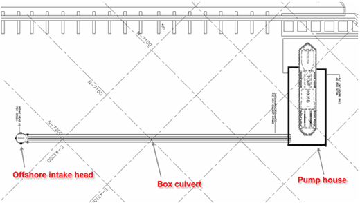
Layout of intake head, box culvert, and pump hose.
The NS3 system has been applied to model the flow in the new pump structure including evaluation of head loos through the new arrangement of pipes, free surface, study of potential resonance, sediment transport, and deposition in the pumping house.
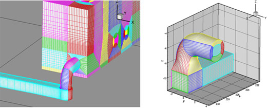
Examples of computational grids
The entire system from the intake head to the pumping house has been modelled in the NS3 model. Beside the global model, a number of detailed models were also developed in order to investigate local flow patterns in details, for example flow and pressure in specific parts of the system, i.e. 90o bends between two pipes.
Model results
The NS3 simulations of the entire system did reveal that with the original design surface elevation in the pumping house would be very close to a critical level during pump start. Hence the layout of the pipes had to be redesigned in order to minimise the head loss and obtain an acceptable water level in the pumping house.
Local detailed models were used to model the sediment transport and deposition in the pump house to investigate whether the deposition of sediment would reach a critical level within a given time. Furthermore the near bed velocities in the pump house were used for design of scour protection material. A local model around the offshore intake head was used as part of an environmental impact assessment at the coastal area around the intake.
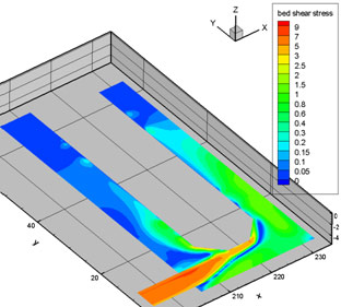
Bed shear stress in pump house